6.6. Test box measures
Section 6.6 author – Stuart Whyte
Introduction:
There are UK quality standards and practical guidance on electroacoustic measures for HAs, BCHDs, and auditory implant sound processors – most commonly CIs.
‘Quality Standards for the use of personal FM systems’ by the UK Children’s FM Working Group was published in July 2008 by the NDCS. This was updated in February 2017 as ‘Quality Standards for the use of personal radio aids: Promoting easier listening for deaf children’. The multi-agency group is now known as the UK Assistive Listening Technology Working Group (ALTWG).
The latest version of the guidance on QS8 Electroacoustic checks with auditory implants was published in March 2024
Of particular relevance is Section 5 of the Quality Standards on the Management and use of personal radio aids, which includes QS7 and QS8.
QS7: Subjective checks of radio aids must take place regularly.
Perform listening checks of the radio aid system daily, with and without the hearing instrument, using appropriate devices such as a stetoclip for hearing aids, monitor earphones for cochlear implants, listeners for bone conduction hearing implants, or a dedicated headphone set for the radio system.
QS8: Electroacoustic checks must be performed regularly and whenever a part of the system is changed.
Complete regular (test box) checks in order to compare the frequency response curves with baseline settings provided at the time of set-up.
A good practice minimum is every half term – this may need to be more often for young children and will depend on the user.
Explanation
Terms used
Hearing device is a catch-all term for hearing instruments and includes auditory implant sound processors, HAs, and BCHDs. The most common auditory implant devices are CIs.
Remote microphone (RM) system is a catch-all term for proprietary microphones associated with specific hearing devices and general radio aids. Systems can be directly connected to the hearing device with dedicated cables or by making use of the telecoil in the hearing device with induction-loop systems.
Health and safety
It is important that health and safety is considered. For example, neck loops are not recommended for young children. Also, induction-loop systems are vulnerable to electromagnetic interference and general performance may be affected (see also the comment below on test box responses). For young children, vulnerable young people, and adults, a proprietary battery lock should be fitted (see ‘Further reading’).
As part of routine checks, such as listening to hearing devices prescribed to others or evaluating hearing in a soundfield, it is essential to protect the tester’s ears with appropriate attenuation, for example, a stetoclip with a variable attenuator or ear plugs and ear defenders. This type of personal and protective equipment (PPE) needs to be considered alongside hand hygiene, and infection prevention and control products.
Test boxes are heavy, sotake care when lifting and handling them. It is useful to consider wheeled cases for transport and appropriate care of components when transferring between venues. You do not want things to move about and get damaged.
Subjective checks
It is important to first listen to the whole system together and then to its separate components when troubleshooting. The whole system comprises the hearing device and its connection to a receiver and an associated transmitter:
hearing device receiver transmitter
All parts of the chain of communication should be checked with a stetoclip or monitor earphones (device dependent) (see ‘Further reading’).
Electroacoustic checks
A visual and listening check should always be carried out before test box measures are made. Regular checks compare the frequency response curves with baseline settings provided at the time of set-up.
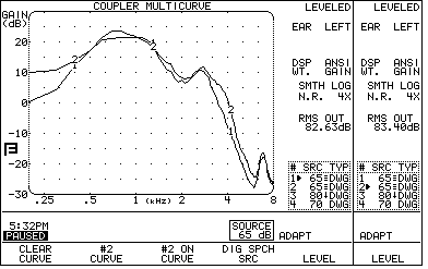
The most common measures to record for hearing devices are responses to sounds at soft, conversational, and loud levels; and to check for distortion. The aim is to make regular comparisons against a baseline recording to see if performance is still appropriate. For tests 1 and 2, use the international speech test signal (ISTS) or an equivalent speech-like signal. On the Fonix FP35, DIG SPCH is required.
- Frequency responses in SPL (sound pressure level) should be recorded as 50, 65, and 80 dB.
- The test box should be set to GAIN and curves repeated at 50, 65, and 80 dB.
- Total harmonic distortion (THD).
The most valuable test is GAIN; given time pressures in the field, it may be best to focus only on Test 2. Gain curves are also used for ‘balancing’ remote microphones with hearing devices (see section below).
For the set of curves in test 1, the response to 80 dB will be the highest curve and the 50 dB curve the lowest. The 65 dB curve will be in between. Check that these curves match baseline records.
For the set of curves in test 2, the response to 50 dB will be the highest curve and the 80 dB curve the lowest. The 65 dB curve will be in between. Check that these curves match baseline records.
What if the curves are different?
Replaceable microphone filters should be changed regularly. Your visual and listening checks before using the test box would have revealed actions to be taken before testing. For example, moisture or wax (or worse) may be occluding the tubing connected to the HA, or the filters on the CI processor can be blocked.
Does the user notice things sound differently?
Despite remedial action, if performance is degraded then refer to the user’s local audiology or auditory implant service. If there are contraindications to testing in the first instance, for example, noticeable infection or acute odour, then parents/carers should be asked to seek medical advice.
Test 3: As speech noise is made up of multiple frequencies, it cannot be used as an input to measure distortion. Total harmonic distortion THD is a calculation between the fundamental frequency and the intensity of subsequent harmonics. THD can only be measured with a tonal stimulus as each tone is presented with equal energy. Ideally, distortion will be below 10%. However, for digital signal processing (DSP) devices, THD may appear artificially high (15% or more as harmonics are given greater energy than the fundamental in channels with DSP). When measuring distortion, take a note of the reference level (even if it is high) as the level should be repeatable over time (the same DSP). Where there are large changes between periods of measurement, refer back to the service that fitted the device.
Different test box options
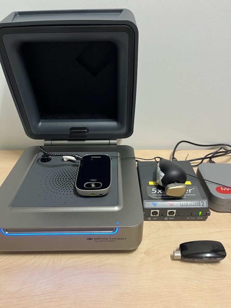
There are three common test boxes in use today in the UK (others are also available): Frye FONIX FP35, Affinity systems, and Aurical Hearing Instrument Test (HIT).
The Affinity and Aurical systems meet modern requirements for testing hearing devices (BSI 2021; 2022) and have the ISTS. The FONIX FP35 Analyzer needs to have the latest software to be able to select ‘Aid Groups’ as ADAPTIVE and to select the test signal DIG SPCH (digital speech). DIG SPCH is an interrupted composite signal and is not equivalent to ISTS. In addition, measurement tolerance is higher with the FP35 (see tolerance section below). The latest FP35 software is also needed to test modern HA fittings with an Open Fit Coupler.
Telecoil (t-coil) responses are known to be reduced in the lower frequencies to avoid interference in this area (Putterman & Valente, 2012). Therefore, in all test boxes, induction-loop RM system curves will be reduced in the lower frequencies and the response curves are more likely to match above 1 kHz.
Other equipment needed
Dedicated monitoring/listening components are necessary for some hearing devices. The Connevans DCTEST4 lead and earpiece (button receiver) allows baseline measurements to be made in a HA test box. It can also be used with Advanced Bionics Naida CI, Naida CI M, or Sky CI M processors with their dedicated listening checks; and Cochlear N7 and N8 processors. It is also compatible with the MED-EL SONNET and RONDO processors, but additional accessories are required (see ‘Further reading’).
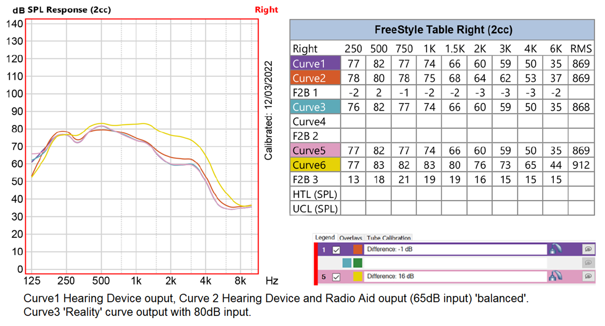
Balancing (acoustic transparency): verification and validation with RM systems
We verify to ensure that the level and quality of sound a child hears through the RM matches what they hear through the microphone of the sound processor. If the gain of the system is too low, it will make little difference to the user and their access to spoken information is disadvantaged. They can soon become disenchanted and reject the resource. If the gain is too high, compression in the whole system could lead to distortion.
People with sensorineural deafness have a reduced dynamic range between the softest sounds they can hear and the loudest sounds that are comfortable to hear. Suitable levels are crucial, even more so for CI users because the dynamic range of cochlear stimulation is further reduced. Dynamic range has implications for both speech perception and sound quality. The normal-hearing dynamic range is between 0 dB and 120 dB. The hearing device reduces sound detected by its microphones to an input dynamic range (IDR), ie very soft sounds are omitted and loud sounds are compressed. IDR is manufacturer dependent. In a CI sound processor, this is compressed to about 40 current units, and further signal processing produces a narrow electrical dynamic range for each electrode channel (Wolfe & Schafer, 2015).
Balancing RM systems with HAs and BCHDs
Actions for proprietary microphones (generally manual gain or non-dynamic systems)
The signals presented to the hearing device and to the RM are equal and at 65 dB SPL.
| Device | dB SPL level to device | dB SPL level to RM |
| HA or BCHD | 65 | 65 |
- Record the frequency response of the hearing device to a speech signal of 65 dB.
- Connect the receiver (if necessary) to the hearing device and activate/pair the RM.
- Record the frequency response of the whole system to a speech signal of 65 dB to the RM.
- Check that responses 1 and 2 are within 2 dB and within the tolerance value of the test box (see ‘Tolerance’ section below).
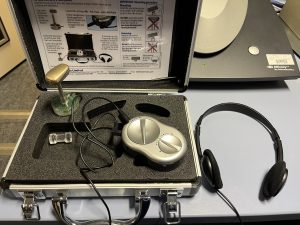
For BCHDs, specialist equipment is needed. A clinical skull simulator is the most accurate device, but proxy measures can be recorded with a kit provided by Connevans.
Although responses may be elevated in the test box using the Connevans kit in comparison to clinical results, they are comparative with the same hearing devices across test boxes. For example, frequency response of a Baha 5 sound processor in an Affinity system and a Fonix FP35 were found to be within 1 dB with the Connevans kit.
Skull sim:
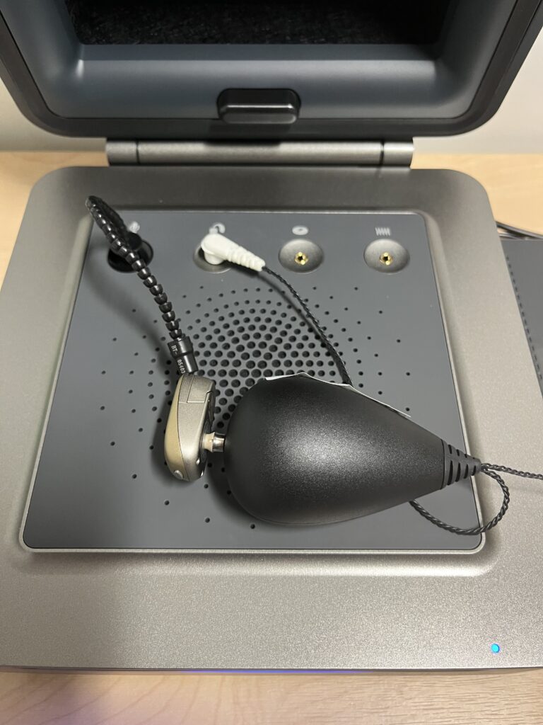
Connevans kit:
Actions for dynamic radio aid aids, eg, Phonak Roger systems
The signals presented to the hearing device and to the RM are equal and at 65 dB SPL.
| Device | dB SPL level to device | dB SPL level to RM |
| HA or BCHD | 65 | 65 |
- Record the frequency response of the hearing device to a speech signal of 65 dB.
- Connect the receiver (if necessary) to the hearing device and activate/pair the RM.
- Activate Verification Mode* on the transmitter (RM).
- Record the frequency response of the whole system to a speech signal of 65 dB to the RM.
- Check that responses 1 and 2 are within 2 dB and within the tolerance value of the test box (see ‘Tolerance’ section below).
* Verification Mode is required as the transmitter is not able to act dynamically to current test signals. In order to fix this variable, Verification Mode sets the system gain at 10 dB. In standard mode, the system can provide up to 20 dB of gain.
Balancing RM systems with CI Sound Processors in non-clinical settings
| Device | dB SPL level to processor | dB SPL level to (RM) |
| CI sound processors | 65 | 65 |
An acoustic transparency method with signals of equal intensity can be used with all hearing devices, even with non-linear signal processing (Husstedt et al, 2022).
Electroacoustic test signals in quiet clinical settings
Some CI processors have first-stage compression that can be observed. Although signals of 65 dB SPL can be used, it may be useful to present a softer signal to those processors where possible (Whyte, 2019).
| CI processor | dB SPL level to processor | dB SPL level to (RM) |
| All Advanced Bionics processors | 65 | 65 |
| Cochlear Nucleus 6 and above | 55 | 55 |
| MED-EL SONNET and RONDO series | 55 | 55 |
It is thought that signals of equal intensity will be similarly compressed by implant sound processors, and a signal below the compression level may not be necessary (Husstedt op cit). Further research is being conducted to establish the suitability of signal levels through qualitative methods and behavioural testing.
Tolerance
Adjust the volume/gain of the RM, or ‘FM advantage’ or ‘EasyGain’ level of the radio aid receiver so that the combined system response curve matches the sound processor response curve and achieves ‘transparency’ or ‘balance’. If the difference is 2 dB larger than the measurement tolerance, then two output signals are different and transparency is not achieved; therefore, continue adjusting. For example, in the Aurical HIT, if the two responses are within 3 dB, then transparency is achieved.
Adjusting the receiver gain should preferably be done by starting at a low gain and then increasing.
| Tolerance or signal accuracy up to 5,000 Hz | Transparency difference overall |
| Affinity < ± 1.5 dB | ± 3.5 dB |
| Audioscan ± 1.0 dB | ± 3.0 dB |
| Aurical ± 1.0 dB | ± 3.0 dB |
| Fonix FP35 ± 2.5 dB | ± 4.5 dB |
Transparency or balance can be judged by eye, by offset calculation, or by root mean square (RMS) values or calculations (see GPGQS8 – ‘Auditory implants’ for details of calculations. Worked examples are available in the ‘Example resources’ section).
Validation
Following fitting and verifying, the balance (electroacoustic transparency) of the hearing device and RM system must be validated. It is vital to assess speech recognition in quiet then in noise, with and without the RM system.
- Ideally, use an adaptive test to evaluate speech recognition performance in noise, which will avoid ceiling (100%) and floor (0%) effects that may occur with fixed stimuli.
- Alternatively, use an SNR test using signal levels that represent the most common environment where the wireless remote microphone (WRM) is to be used.
“Measures of benefit must not only include objective measures, but also patient perception of benefit” Clark et al (2017:617).
Consider using:
- observation
- behaviour
- functional listening
- questionnaires, eg
Clark, J. L., Pustejovsky, C., & Vanneste, S. (2017). Objective and perceptual comparisons of two Bluetooth hearing aid assistive devices. Disability Rehabilitation Assistive Technology, 12(6), 614–617. https://doi.org/10.1080/17483107.2016.1201153
Useful resources
Testing Advanced Bionics (AB) processors in the Aurical HIT Box: AB_AURICAL
Testing Cochlear processors in the Aurical HIT Box: Cochlear_AURICAL
Testing SONNET processors in the Aurical HIT Box: SONNET_AURICAL
Updated – Which test lead do I need? – Updated – Which test lead do I need?
Connevans Are you using the correct test signal in your Hearing aid testbox?
Video resources and other websites:
Interacoustics – How to Improve the SNR in Children with Mild to Moderate Hearing Loss
Test box video demonstrations (Ewing Foundation)
Testing a hearing aid with the Aurical HIT (Connevans)
Setting up a Phonak Roger Touchscreen Mic using the Aurical HIT (Connevans)
Checking a Phonak Roger Pen using the Aurical HIT (Connevans)
Roger verification with Roger On and Roger Select (HASS Group)
Setting-up an fmGenie using the Aurical HIT (Connevans)
FP35 Hearing Aid Analyzer PowerPoint Presentation
Guidelines for fitting hearing aids to young infants
Considerations for QToDs
A Phonak Receiver Audio Checker and adapters are very useful for doing listening checks with Phonak Roger X receivers (additional adapters are required for the range of other Roger receivers).
- Phonak – Using the Roger X / MLx Audio Checker
- Connevans –Phonak Roger 21 Checker
- Connevans –Phonak Roger 20 Checker
- Connevans –Phonak Roger 17 Checker
- Connevans – Phonak Roger 14 Checker
- Connevans – Phonak Roger 19 Checker
- Connevans – Phonak Roger 18 Checker
- University of Southampton – Testing SONNET processors in the Aurical Hearing Instrument Test (HIT) Box
- University of Southampton – Testing Cochlear processors in the Aurical Hearing Instrument Test (HIT) Box
- University of Southampton – Testing Advanced Bionics (AB) processors in the Aurical Hearing Instrument Test (HIT) Box
- Ewing Foundation – Which test lead do I need?
It is important to maintain up-to-date software and firmware
-
- Phonak –Roger™ Upgrader
- Phonak –Phonak Roger Upgrader™
Hearing device settings
Has the hearing device been set up to use the RM? What settings need to be present or activated?
For children and young people, mixing ratios of the processor microphone and aid radio aid should be 1:1 or 50:50.
If a loop system is to be used, does the telecoil need to be enabled?
Are there features active in the hearing device that may affect performance in the test box, eg directionality or phone detection? Remember to do like-for-like comparisons against baseline recordings.
Further reading
Guidance: Using button and coin batteries
- Gov.uk- Using button and coin batteries
- NHS (England), 2014 – Risk of death and serious harm from delays in recognising and treating ingestion of button batteries
- Tamper-proof options or additional housing kits to secure battery access is required for children under 36 months, for vulnerable users, or if there are other young children in the setting.
- NDCS Briefing paper (2018) Radio aid usage with children aged under 36 months
Standard infection control precautions
-
- NHS England –Chapter 1: Standard infection control precautions (SICPs)
- NHS National Services Scotland – National Infection Prevention and Control Manual
- https://phw.nhs.wales/services-and-teams/antibiotics-and-infections/infection-prevention-control/
- NHS Wales Public Health Wales –Infection Prevention & Control
- Public Health Agency Northern Ireland – Infection Prevention and Control Manual
- BATOD – Cleaning hearing devices and radio aids – supporting health and safety during Covid-19 guidance (June 2021)
QS7: Subjective checks
- Maltby, M.A., & Knight, P. (2000). Management and Maintenance of Hearing Aids in Audiology: An Introduction for Teachers & Other Professionals (1st ed.). London: Routledge.
- McCracken, W., & Laoide-Kemp, S. n. (1997). Audiology in Education. Appendix C pp. 423–433. London: Whurr Publishers.
- Connevans – Cochlear Nucleus 7 & 8 Monitor earphones and adaptor
- How to use your Naida CI: Listening check video
- How to use your Marvel CI: Listening check
- MED-EL Rondo 3 – Testing the Microphones
- RONDO processors need the mini battery pack for connecting Roger X receivers (video). They can be checked in the test box in conjunction with a RONDO connection cable and a MED-EL microphone test device.
QS8: Electroacoustic checks
- Assistive listening technology Working Group – Good Practice Guide for Radio Aids – QS 8
- Assistive listening technology Working Group – Good Practice Guide for Radio Aids – QS 8 (Auditory implants)
- ASHA (2002). American Speech-Language-Hearing Association: Guidelines for fitting and monitoring FM systems [Online] (Accessed 28 May 2023).
- Evans, D. (2006). fm Advantage Procedures for the setting up of fm radio aid systems for use with hearing aids. V.3.0. Connevans.
- Husstedt, H., Kahl, J., Fitschen, C., Griepentrog, S., Frenz, M., Jurgens, T., & Tchorz, J. (2022). Design and verification of a measurement setup for wireless remote microphone systems (WRMSs). International Journal of Audiology, 61(1), 34–45.
- Whyte SD (2019) Validating fitting protocols for design-integrated radio aid receivers and cochlear implants. Presented at the British Cochlear Implant Group Conference 2019: Connecting for Life. Southampton.
Test boxes
- Connevans –Advanced Bionics, MED-EL & Cochlear Nucleus 7 & 8 test lead & button earphone
Naida CI or Naida CI M listening checks are needed to connect the DCTEST4. - Connevans –Cochlear Nucleus 7 & 8 Monitor earphones and adaptor Also compatible with N8.
- A jack adapter is required for the Monitor adapter to allow DCTEST4 connection
- Connevans –MED-EL Microphone Test Device Kit for SONNET and SONNET 2
- MED-EL AudioLink
FP35
Interacoustics Affinity system
- Affinity 2.0 Equinox instructions for use
- Affinity 2.0 Support
- Affinity Compact – Instructions for use
- Affinity Compact Support
Natus Aurical system
Standards
- British Standards Institution (2021). BS EN ISO 21388:2021. Acoustics — Hearing aid fitting management (HAFM). London: British Standards Institution.
- British Standards Institution (2022). BS EN IEC 60118-16:2022. Electroacoustics – Hearing aids: Part 16: Definition and verification of hearing aid features. London: British Standards Institution.
Practicalities
- DPA Microphones – Facts about speech intelligibly
- e ITU Radiocommunication Assembly – Recommendation ITU-R BT.1359 Relative timing of sound and vision for broadcasting
- ITU-T Rec. P.1305 (07/2016) Effect of delays on telemeeting quality
- EBU – Speech Intelligibility in TV
- Lester, M., & Boley, J. (2007). The Effects of Latency on Live Sound Monitoring. Journal of the Audio Engineering Society.
- McGrath, M., & Summerfield, Q. (1985). Intermodal timing relations and audio-visual speech recognition by normal-hearing adults. Journal of the Acoustical Society of America, 77(2), 678–685.
General
- BSA – hearing-balance (visit the BSA website via this link for most recent publication)
- BSA Guidance documents
- Fiztpatrick, E. M., & Doucet, S. (2013). Pediatric audiologic rehabilitation: from infancy to adolescence. New York: Thieme Medical.
- Madell, J. R., Flexer, C., Wolfe, J., Madell, J. R., Flexer, C. A., Wolfe, J., & Schafer, E. C. (2019). Pediatric audiology: diagnosis, technology, and management (Third ed.). New York: Thieme.
- Putterman, D. B., & Valente, M. (2012). Difference between the default telecoil (t-coil) and programmed microphone frequency response in behind-the-ear (BTE) hearing aids. Journal of the American Academy of Audiology, 23(5), 366–378.
- Wolfe, J., & Schafer, E. C. (2015). Programming cochlear implants (2nd ed.). Plural Publishing.
Next page in this section
6.7 Other hearing technologies
Previous pages in this section
6.1 Hearing aids
6.2 Bone conduction hearing devices (BCHD)
6.4 Assistive Listening Technology (ALT) – radio aids and proprietary remote microphone systems
Other sections
- Section 1 Anatomy and physiology of the ear
- Section 2 Aetiology and types of deafness
- Section 3 Auditory perception and hearing testing
- Section 4 Acoustics and physics of sound
- Section 5 Listening skills and functional hearing